Tuesday, May 17, 2011

Final Project--From Lego to Delrin!

Now that we had a full Lego prototype of the physical aspect of our project, it was time to turn everything into Delrin!

Well, not quite everything.  We decided to use Lego gears since I had learned from my experiences with the Gearbird that it is very difficult to use SolidWorks to make a gear the exact size you want it to be, since you can't select the diameter.

Since we were using Lego gears, everything had to be built EXACTLY to Lego scale.  This meant a lot of time spent figuring out the exact dimensions of various Lego parts. As a result, we really learned to love the FLU (fundamental Lego unit, not the illness).

Also, quick side note: We decided to give up on the initial stage one of our creep in the box, the wolf whistle.  We felt as if we had enough on our plates with what we were already doing, and it seemed that the only way we would have been able to project a wolf whistle would have been by hooking our robot up to a computer, which seemed rather inconvenient.

Anyway, back to Delrin!

What needed to be done:

Construct a delrin box that would move up and down the linear gear track using its gear trains (which would protrude slightly from the sides).  The box structure would also be responsible for stabilizing the scissor mechanism (i.e. stage two), which would rest on top of it.

The box would consist of 4 pieces: top, bottom, and two sides

(Very) General Plan

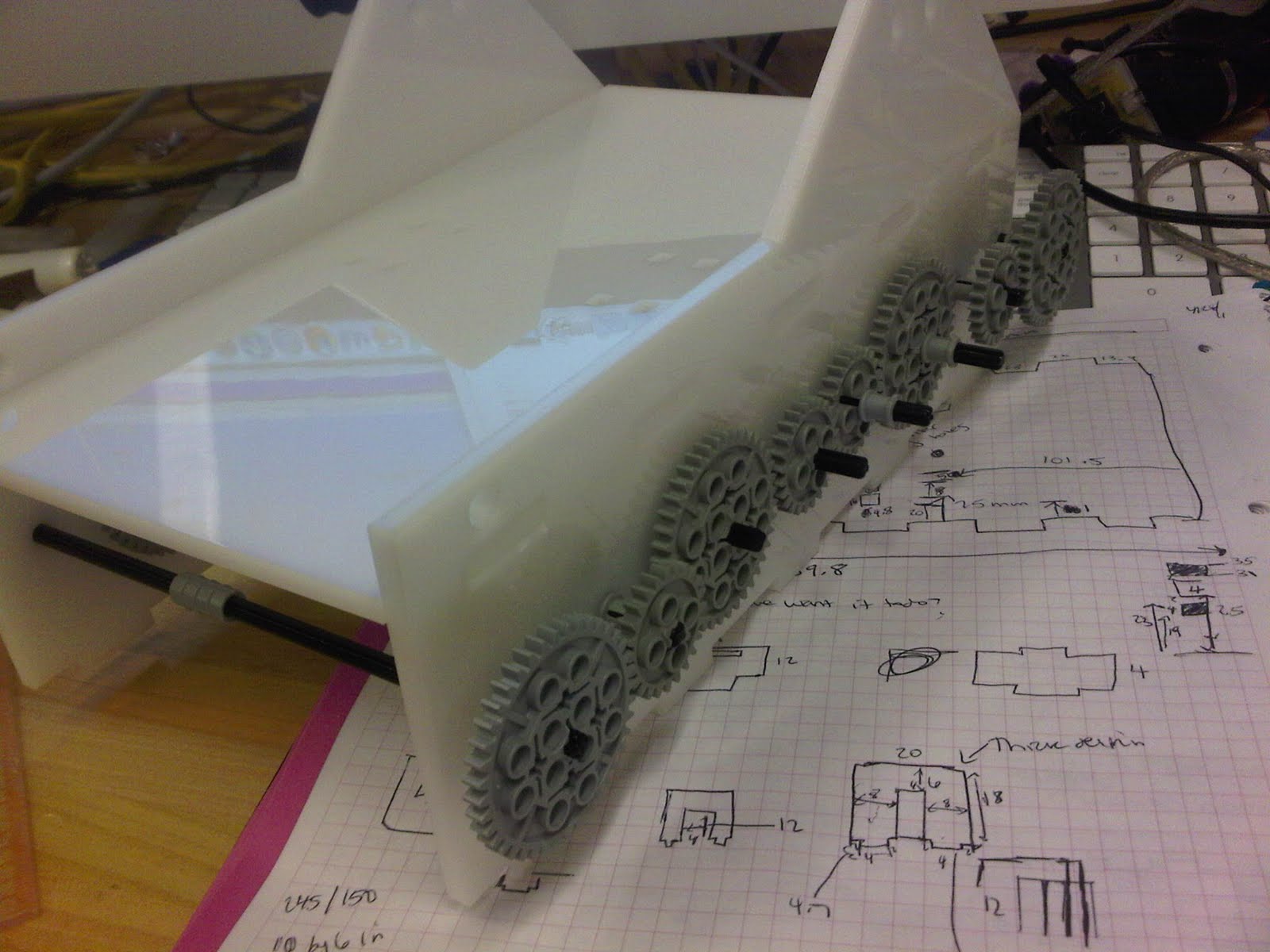
Measurement-wise the sides of the box were the most complex, so I began with them.  After close examination of our Lego prototype, it seemed that the sides needed to:

1. Have eight correctly spaced holes (4.8mm for Lego rods) for the gear trains
2. Have one hole (.25mm for a Delrin rod) each to stabilize the base of the scissor mechanism
3. Have two holes (.25mm for a Delrin rod) each, raised above the general structure, to help support the stage two motor
4. Connect via press fit to the top and bottom of the box

Constructing the side on SolidWorks was a long process--it began with step 1 (figuring out the gear dimensions), then continued to steps 2 and 3 (finding exact measurements for stabilization rods), and finally step 4 (figuring out press fit dimensions).

To figure out the spacing of the gear holes, I built this visual aid:


The wonders of the internet gave me all of the information I needed to know about Lego dimensions: 4.8mm holes, 3.2mm between holes, 5.5mm between the last hole and the end, and 9.6mm height.  With these dimensions, I was ready!

Below is the process of making the side of the inner box, and the final SolidWorks version:


Some press-fit trial and error took place on small, sample pieces of Delrin so that the press-fit dimensions on the much larger box pieces would be correct.
Press fit trial and error

SolidWorks side part with added press fit protrusions
If you look back at the general plan:
 The press fit protrusions were on the top and bottom of the box, and the holes were in the sides.  I reversed the placement of the protrusions and holes so that the top and bottom of the box could lift on and off if necessary, instead of being forced to pull the sides apart, which would be covered with gears.

Clara and I decided to wait until slightly later to design and print out the top of our box, since we wanted to use press fit pieces to help stabilize stage 2.  In the meantime, we printed out the two sides and the base.

Sketch of one side and bottom

Miraculously, the sides were dimensioned correctly and fit the gears on the first try!!
SUCCESS!
The inside of the inner box

Since all of the gears are connected to one motor, they will be turning at the same speed as their mirror image gear on the other side of the box.  The rods between the gears in the picture above are for added stabilization.  It turned out that these rods alone did not provide enough stabilization, and at a later stage in our building I added some more:

Stabilized!
All the measurements were based exactly on the Lego model, which is how I was able to figure out how to place the non-gear holes in the box's side.  The one measurement we did change was the width of the box, since we wanted a bigger base for our creep.

In the meantime, Clara had been building a delrin version of the scissor mechanism.  This involved printing many Delrin donuts and scissor pieces (almost all identical, with two shorter pieces), and attaching them with small pieces of Delrin rod. She too had used exact Lego measurements, so that the scissor mechanism would line up exactly with its stabilization holes in the box's sides.

Laser cutting pieces
Scissor gear, before the donuts had been converted to delrin (these donuts were far too heavy for our mechanism)
In the process of converting
Again, miraculously, this stage 2 mechanism lined up exactly with the holes!  Clara and I realized that we clearly had a previously undiscovered talent for measuring things.

Here is a sketch and SolidWorks drawing of the top:


The small holes are for tiny press fit arch supports to keep the forward-motion part of the scissor mechanism moving forward.  Without the small arches, the pieces popped up a little bit, reducing the strength of our pop.

 
Press-fit test for arch

Arch size check--the piece needed to be able to freely slide back and forth


Top in place! (If you look closely, you can see the tiny arch holes)
Full box!


Now that all of the pieces had been printed, we were finally able to assemble our mechanism for the first time!
Everything fit!


Popping!
We were very excited to see that everything fit.  We did see however, that the motor still desperately needed to be stabilized.  We remedied this in two ways:

1. The Lego rods were very flimsy.  Additionally, rather than being at the same height, one of the bars should have been slightly lower in order to hold the motor at the right angle.  We didn't want to completely reprint both sides, which would also entail reassembling all of the gears, so we found an alternate solution: steel rods!

The steel rod was of course much stronger than the Lego rod, but we could only put in one since steel doesn't bend like Lego does, and our second support rod needed to bend because its hole placement was slightly off.  It turned out though that the second support rod was not even necessary--the steel was so strong that it did the job by itself!


2.  The motor still slid from side to side, so we decided to print a larger version of the tiny stabilization arch to go over the motor and hold it in place.  This required re-printing a new top with added holes for the additional arch.  The motor was under a lot of strain, so to ensure the arch support did not pop out of the top, we decided to connect it like this, instead of just with the traditional press-fit:


Solidworks drawing

The piece goes all the way through the top, where it can be secured from below with a Lego rod.

We printed the arch and a new base.  Once again, everything fit, which made us very excited.  The arch did a great job of holding down the motor.


New arch!


Just one arch was necessary!
New Solidworks top!


Solidworks Drawing

Final Project--The building begins!

With our general goals in mind, we set to work building a model of our robot out of Lego.

Clara and I decided to divide and conquer, so she focused on trying to figure out the best popping mechanism for stage two while I focused on figuring out how to build a creep elevator for stage one.

After thinking about potential pully or cam mechanisms, Lyn showed us the wonder that is the linear gear, and we decided the best way to elevate our creep would be by using the linear gears and a gear train.

An early sketch with possible elevation ideas

Gear train preliminary sketch.. the caption is very necessary in this case.
As you might (or might not) be able to see from my scribbled notes, we were not sure if the gear train would have enough torque to lift the creep's platform.  The only way to find out was to build it and see, so we set to work.

I built this primary structure, then started working on the gear trains.  It took a while to figure out the correct gear ratio.  We needed a gear train that would allow for slow elevation without having too much torque. (We didn't want our creep to elevate too fast, since that would make him lose some of his creepiness.) Here is the process:

Linear gear track
Close up: Linear gears!
We started with mini gear trains..

Two mini gear trains

Attached them to the motor...
Put it all in a Lego box...
And tried out the structure for size!


The linear gear idea seemed like it would work, so it was time to go big and build a full-sized gear train:

Linear gear posts--one for each corner of our elevator-to-be

One of two gear trains
After attaching a motor between the two gear trains,  and a Lego bottom and top, our initial stage one mechanism was complete! Here are the gear trains in action (with the top of the Lego box removed):


Finally, after much trail and error and with fingers that had been slightly mangled by too much gear handling, it was time to test out the elevator!


In case you can't tell by my squeals of excitement, it worked!  We put a textbook on top to simulate the weight the elevator would need to carry, and it did a great job.

As you can see the four linear gear posts require a great amount of stabilization.  We planned to connect them to the sides of our creep box, which would require the box to have very accurate proportions.

Now that stage one existed, it was time to figure out how to connect it to stage two. 

After experimenting with various ratchet and spool mechanisms, Clara had the idea to use a scissor-like mechanism to lift our creep head.  She whipped up a lego version, and we attached it to the stage one base.  We were both very excited about this idea, because it seemed much simpler and more plausible than our previous stage two mechanism ideas had been.

Experimenting with ratchet idea

Scissor mechanism!

The scissor mechanism is connected to the motor on the right by two more of the same sort of pieces it is made out of--one the same size (lying flat on the top), and one slightly shorter (connected to the motor).  When the motor rotates, it causes a forward motion, which in turn activates the scissors.  The piece lying flat on the top is forced to go only in a forward motion, instead of possible up/down or side to side motion, by the little Lego stabilization box above.

We then tested the mechanism out with the motor, to see if it would work.


As you can see the mechanism worked, but lacked much stability.  We were not able to stabilize it using Lego, but planned to build our delrin structure so that it would be able to stabilize everything.  Additionally, we decided to double the scissor mechanism to give it some more power and stability.  We planned to attach the head to spring on top of a small (and very light) platform on the top of the scissor mechanisms.

Final Project--The idea takes shape!

The next week, we went on a field trip to Tufts where we were to present more detailed versions of our top two ideas to Lyn, Chris, and the class.

At this stage, Clara and I had already nearly decided to pursue our creep idea (who am I kidding, we had practically made our decision the moment we came up with the idea), so we focused most of our attentions on him.

We came up with this more detailed game plan:


Having decided what we wanted our creep to do, the next step was to figure out how to make everything happen.  We divided our creep's main actions into two steps, stage one and stage two.

Stage One: The initial creeping motion, activated by person approaching creep.  

We wanted our creep to peer above the lid of his box using some sort of elevator mechanism, and potentially move back and forth slightly.  We thought we might be able to accomplish this 'looking around' motion by putting a magnet in the creep's chin, and another, somehow mobile, magnet in the rim of the box.  We thought the magnet in the box could be on some sort of track so when it moved, it pulled the head slightly along with it.

Note: Quite soon in our building process we decided that, since the creep's ability to look back and forth was not vital to our project and we already had a lot going on, we could abandon the magnet idea.

Stage Two: The pop!

For stage two, we needed some sort of mechanism that would allow our head to pop quickly, since a slow pop doesn't scare anybody.

We had a variety of initial ideas for this mechanism:

One involved a motored spool (motored in one direction, free rotating in the other), bungie cord, and motor controlled lever.
Initial idea for stage two mechanism
Our idea was that the motor controlled lever would hold down the creep head, which would be held taut by the bungie cord.  When the lever released, the head would shoot up because of the taut bungie, before being reeled back by the motorized spool.

Another idea we had was very similar to the first idea in principle, but involved a ratchet instead of the motored spool.

After our brainstorming session, Clara and I were very excited to get to work to see if our ideas would be successful!

Final Project—Brainstorming!

After receiving our final project prompt to build a puppet, my partner Clara and I set to work with much excitement.  We came out of a wonderful brainstorming session with four possible ideas:

1. Rock Paper Scissors Gloves

This idea was less of a puppet, and more of an interactive game.  It revolved around building and programming gloves using flex sensors.

Idea: Each participant would don a glove and then proceed to play rock paper scissors.  The glove would identify each player’s hand position and transfer it to a display which would lift a rock, paper, or scissors symbol for each player respectively.  The display would also keep score, and celebrate the winner in some way.

2. Battle Bots

Out battle bots idea used the same kind of flex sensor glove as our rock paper scissors idea.
Battle Bot!
Battle participants would each don two flex-sensor gloves and with them, be able to control their robot's movements using their hands.  Each battle bot (pictured above) would have two, independently controlled wheels.  Each glove would control one wheel, and using their gloves the participants would be able to control the direction of rotation of the wheels, as well as have the power to brake them.  We decided that pointing one's index fingers forward would move the wheels forward, sticking one's thumbs up would make the wheels turn backward, and making fists would make the robot to stop.  Using various combinations of these movements, the competitors' challenge would be to maneuver their robot in such a way that it would be able to hit the touch sensor on their rival's robot.  The first player to do so would be the winner!

3. Weather Bot

The purpose of the weather bot was to be a fun, desktop companion.  The user would be able to input the day's temperature (hot/mild/cold) and precipitation (none/rain/snow), and the robot would act and dress appropriately.  The robot would have various accessories to choose from (umbrella, snowboard, beach towel), and via some sort of mechanism (perhaps a magnet) would lift them when necessary.  We decided that our robot would be standing in front of a backdrop that would also have the ability to rotate, as necessary.

My beautiful sketch of potential backdrops
 During our brainstorming session, Lyn told us that it might be possible to hook our robot up to some sort of smart phone so that it could take weather information offline.  This was an exciting feature, and gave our robot the potential to turn from a fun desktop companion to a useful, interactive robot thermometer.

And finally, (drumroll please):

4.  Creep in the Box!

This was actually our very first puppet idea, but I chose to write about it last to make things slightly more suspenseful.  Our idea for the creep in the box was basically to make an interactive (and creepy) jack in the box.  The idea for the creep himself came from SNL’s Lonely Island video “The Creep,” so we knew from the get-go that our puppet would have mustache, slicked-back hair, and shady glasses.  We decided that our creep would have 3 stages, as illustrated in our initial sketch below:


Stage One: When an unsuspecting person comes within 10 feet of our creep, he wolf-whistles to get their attention.

Stage Two:  Interest piqued by the wolf-whistle, unsuspecting person begins to approach mysterious box.  When they come within 5 feet of the box, the top of the creep’s head slowly emerges, and he start peeping out of his box (i.e. creeping).

Stage Three:  If the unsuspecting person hasn’t already been scared away by stage two, they continue to approach the box.  When they reach the box, the creep POPS, jack in the box style, thoroughly surprising the unsuspecting passerby.

We had not come up with any ideas for the physical mechanisms that would make our robot move at this early stage, but we had started to think about how we might be able to use various sensors to trigger each of our three stages.  One idea was to use some sort of hidden touch sensors on the floor that people would trigger as they walked over them.  We also though of possibly using a video camera to sense how far away people were, or of using an ultrasound sensor.

One concern we had at this stage was how our robot would work in crowded areas, since our idea seemed best-suited to be used by one person at a time.

We presented our ideas to the class and got the best feedback on our creep in the box and battle bots ideas, making us excited for the next step in the process..

3/11-14/11

Today in class we experimented with Matlab!  We had a series of mini-challenges, in order to get us accustomed to using the program.

My partner Juliette and I did the exercises together, and this is what we produced:


Our next Matlab challenge involved a DC motor:

Our goal was to build a motor that turned exactly 90 degrees

V_terminal: 5 Volts
K_motor: 0.3 Newton-meter/amp
R: 25 ohms
m (moment of inertia for motor): 0.0001 Kilogram-meter^2
dt = 0.001 (simulation time step)


And victory, we got the time down to 0.25 seconds!


The next class, we added a derivative term and accomplished our goal even faster, 0.1490 seconds! 

3/4/11

Today, our goal was to alter our line followers so that they would be able to drive in a straight line, self-correcting for any mistakes.  We did this by measuring the rotation of each wheel, multiplying the difference by a gain of 0.7, and adjusting the wheel speed accordingly by either adding or subtracting power.

Here is our code:
T

Here is a clip of our follower in action:
 

As you can see, he seems to enjoy tracking to the right.  Both Lyn and Chris looked at our program and couldn't figure out why our robot would be doing such a thing, so we were all slightly confused.  Hande and I decided that our problem must be structural (or that we had somehow come across a motor with a mind of it's own).

Sunday, May 1, 2011

3/8/11

Today's challenge: 
1) Build a controller that turns an NXT motor 90 degrees
2)Using the NXT's data logging features, make a linear model for an NXT motor controller